


- products
- aviation
- example 1
- example 2
- example 3
- example 4
- aerospace
- consulting
- actuators
- electronics
- systems
![]()
Example: Landing Flaps Drive System
We have developed the
entire drive system for the Fowler
landing flaps of a business jet aircraft.
The landing flaps drive system consists of:
|
The key features are:
The systems engineering is according to the conditions of RTCA (DO-160). |
LayoutThe kinematic layout diagram shows the general layout with two motors attached to a common main gear unit, from where the four actuators are driven. The photograph shows the central drive unit (consisting of the two motors and the main gear box) and the four actuators. Not shown are the flexible shafts (several meters long) between the main gear box and the actuators. |
 |
 |
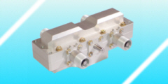
Drive unitOn both sides of the gear box a motor is attached in the middle. The two outputs for the flexible shafts are on the outer corners. |
 |
 |
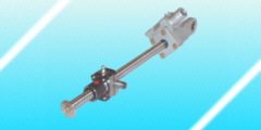
ActuatorIn the actuator acts a worm gear for the additional increase in torque. The conversion from rotational motion to linear motion is made by a ball screw spindle. |
 |
 |