Example: aviation landing flaps drive
Many ultralight aircraft use landing flaps. The operational mode is: driving from the "up"-position to the "down"-position in a safe manner (and back). There is no need for intermediate positions. So we can operate the drive with limit switches which stop the motor.
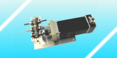
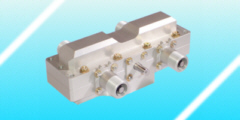
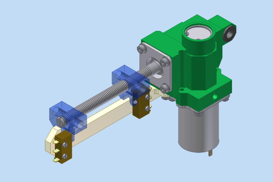
The following CAD screenshot shows such a compact actuator for a landing flaps drive. It consists of a spindle (grey), which operates the nut (blue), which finally operates the landing flaps. The picture has two nuts to show both extreme positions simultaniously. When reaching the final positions the limit switches (brown) deactivate the motor. The housing (green) contains the bearings, but also the reduction gear, which is placed between the motor (grey) and the spindle.
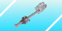
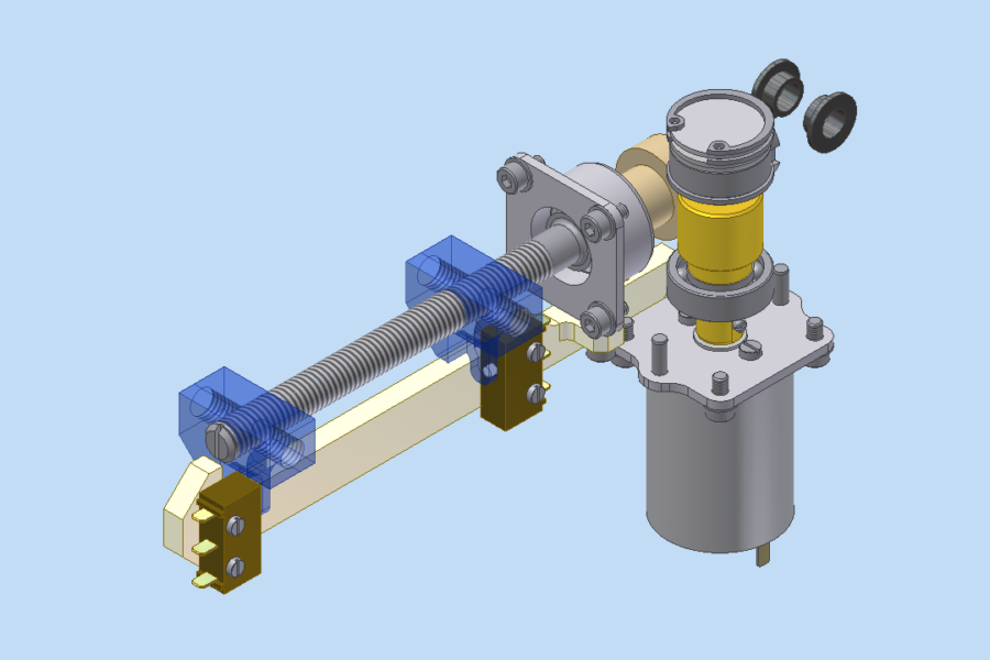
In CAD we can easily hide the housing: so we can show the gear, a worm gear set (yellow, light-brown). The motor (grey) drives the worm, while the worm wheel drives the spindle. It is quite usual to work without a precise manufacturers CAD model (e.g. STEP). On the other hand: the actuator design does not depend on the teeth geometry. It is more important to modify the geometrical shapes to adapt them. So in the design stage we can modify the actuator to different loads and strokes, according to the requirements of the airplane (which happens quite often, since the aircraft is also in the development stage).
Using proven components makes it easier to generate the technical documents (e.g. strength of the fasteners, load capacity of the spindle and the nut, buckling of the spindle, bearing life).