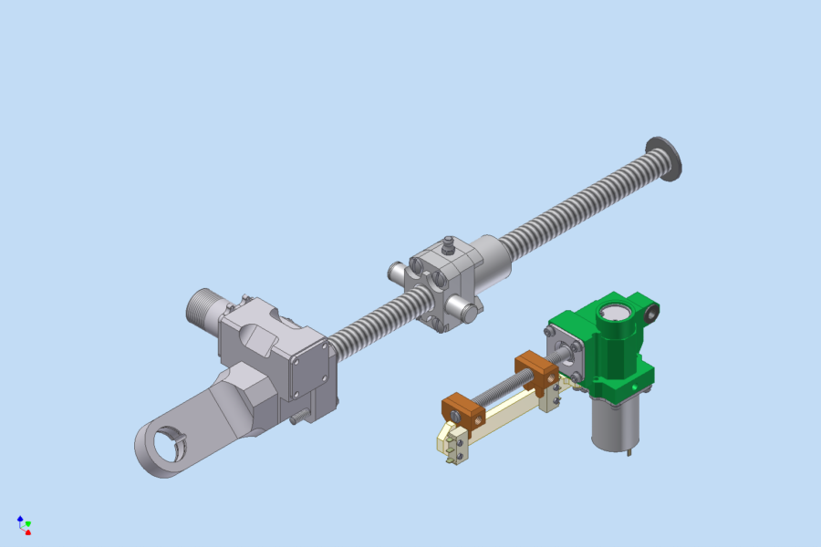

Example: CAD design: actuation system
The design process starts with simple sketches (e.g. to check the available space) and finally leads to the definitive CAD model which is the basis for then manufacturing plans.
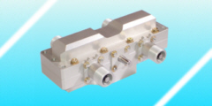
The picture shows a small actuation system in front of a more powerful actuator. In both cases these CAD models were used to check the installation in the CAD aircraft structure ("digital mockup"). Here CAD conversion formats are used. These formats are neutral types of modeling standards which are independent from the CAD system (e.g. STEP models).
The neutral definition of the transfer formats is the reason that these models can be read by most CAD systems without loss of vital information. Therefore it is not important when the CAD system for the design of the actuation system is different from the CAD system for the aircraft design. In many cases we receive a CAD model of the area where the actuation system has to work. So we can design the actuation system to fit perfectly to the geometrical situation. This CAD data exchange saves a lot of time (documenting the interfaces).