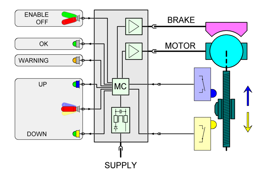
| In the
schematic wiring diagram the control unit boards are in
the center as a grey block with the main components:
protective measures, micro-controller and power stages.
On the left side are the components of the pilot
interface; on the right side are the components of the
landing flap installation (motor, brake, limit switches).
The pilot enables and
commands the control unit. The pilot interface consists
of switches and buttons (to "ENABLE" the unit
and to command "UP" or "DOWN") and
LEDs (to signal "OK", "WARNING" or
the position of the limit switches "UP" and
"DOWN") and is connected to the micro-controller
board. The limit switches, which detect the motion of the
landing flap, are also connected to the micro-controller
board. The micro-controller reads all information and
drives the power stages for the motor and the brake.
|
