|
|||
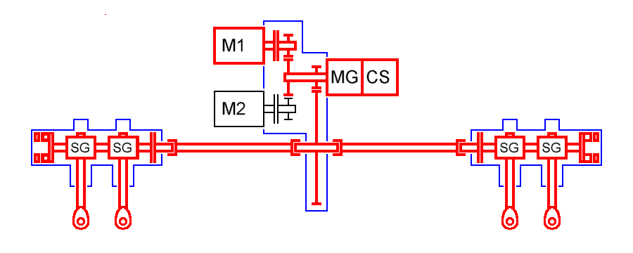
The motors (M1, M2) drive the central summing gear. The output of the gear has two drive shafts for the flex shafts: one shaft to each actuator. Each actuator has two independent trim tab linkages, driven by a worm gear (SG). Each actuator has a position sensor pickup. These data are compared to the other actuator and the position data from the drive unit. The drive unit has a measuring reduction gear (MG) and a position cam switch (CS). By comparing these information the supervising controller can detect failure conditions in the drive train (e.g. rupture) and can act. The friction clutches enable an operation, even when parts of the drive train are blocked. |
|||

|