|
|||
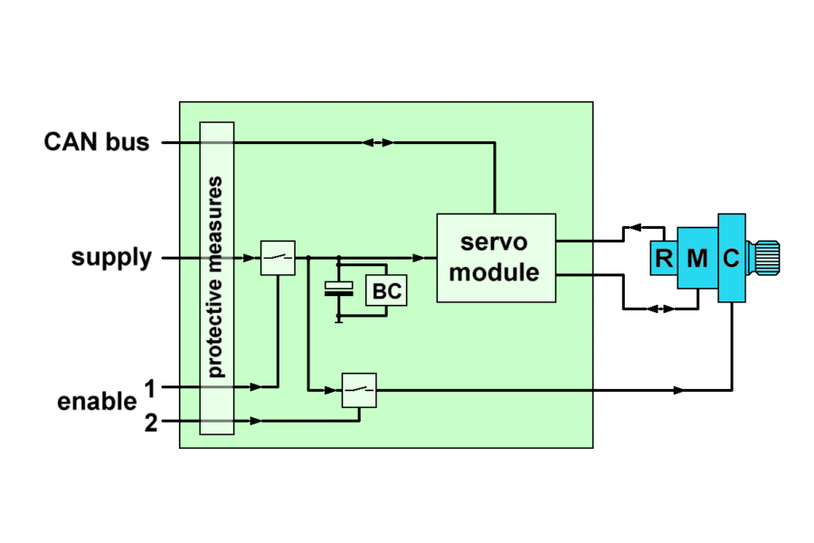
| The
actuator electronic unit drives and controls the
brushless motor (BLDC, "M"). The commutation
sensor is a resolver ("R").
The central servo module processes the commands from the flight control system (CAN bus, enable) as well as the signals from the motor to control the position of the actuator. The power supply and all electric signals are routed by protective measures. These act as: reverse polarity protection, over-voltage protection, under-voltage protection, inrush-current protection, galvanic isolation and the brake chopper ("BC"). The actuator is connected to the mechanical aircraft control system by an electro-mechanical clutch ("C"). The pilot can disconnect the actuator by the clutch to take control. The clutch-enable signal is a signal independent of the servo commands; there are even two independent enable signals to ensure a safe operation even with one signal failed. The two enable signals connect and disconnect the clutch by MOSFET power switches wired between the supply and the clutch. |
|||

|