|
|||
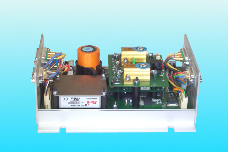
| The actuator electronic unit is built
around a COTS servo module (in the picture: left, in
front), which communicates via CAN bus with the flight
control computer. The key data are: 28 VDC, 15 A. To
operate reliably the unit has several protective measures
(as reverse voltage protection, over-voltage protection,
under-voltage protection, inrush-current protection,
galvanic isolation and the brake chopper.
The brake chopper dissipates the regenerative energy, which can be generated by the motion of the control panel and the actuator and conducted into the power stage. The brake chopper has two stages with two power resistors (in the picture: right). They discharge the dc-link condensator (in the picture: left, in the back) in the case of over-voltage in the dc-link, which otherwise may become dangerous to the servo module. A major topic during development was a modular approach. So we could reach a rapid design process with proven circuits. This meant an increase in the internal wiring, but with the use of high-quality connectors there is no concern about reliability. The external wiring is placed at either side of the unit. The two connectors for the power supply and to the flight control system come from the right and the three connectors for the motor phases, the commutation resolver and the safety clutch come from the left. The protective measures form the biggest part in the electronic unit. In order to save space some cards are stacked up in three levels (in the picture: the right half of the unit). |
|||
|