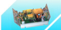
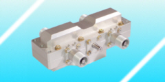
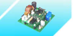
Example: CAD design: electronics hardware
We design the electronics hardware with a CAD system, too. While the schematic defines the interaction of the electronics components (shown in the following picture: in the background), the layout displays the physical representation (front part of the picture). In the electronic hardware design we find again mechanical issues: mainly mounting holes, but also cable routing. Depending on the complexity it may be necessary to create the cable harness as a CAD model to avoid problems with bending radii or cable fixture from the beginning.

The CAD electronics hardware (boards with electronics components, connectors, etc.) is useful to prepare the mechanical design (in a "virtual mockup"). To do so we can generate a STEP model which is then integrated in the mechanical CAD model.

